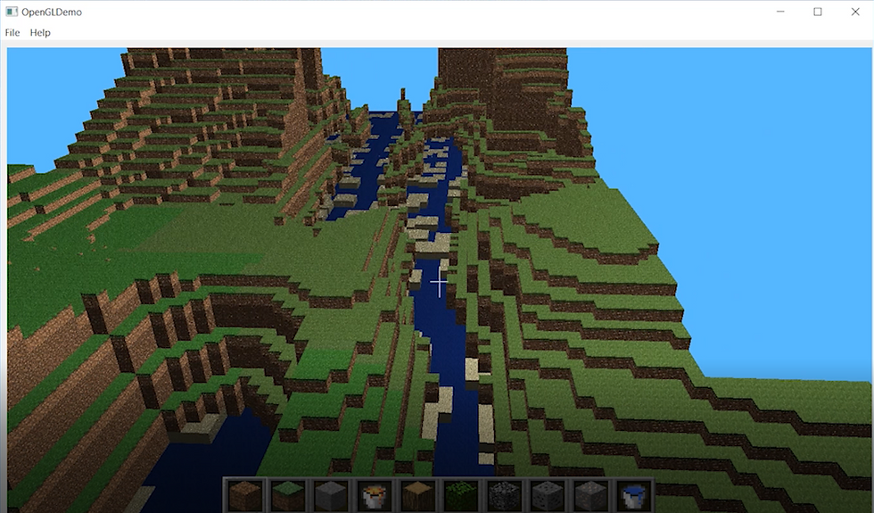
This is a school project done by a team of 3 people. Mini Minecraft is a PC game rendered with OpenGL pipeline. This game supports multiple functions including: automatic terrain generation via Perlin Noise, river generation via LSystem, cave generation via Perlin Worm, deleting and adding blocks, efficient vertex data packing, Blinn-Phong reflection models, animated textures, Biome based grass color, day and night cycle. Among all the features, the last 5 features (from efficient vertex data packing to day and night cycle) are done by me.
Like the official Microsoft Minecraft game, everything in this game is constructed by cube element. To make the rendering more efficient, we send the Vertex Buffer Object (VBO in short) to GPU by chunks, and each chunk consists of 16*16*16 cubes. The VBO for each vertex consists of position+normal+color+other information, and this set of information for all vertice in a single chunk is sent together from CPU to GPU. If we instead send position, normal, color and other vertex data for each vertex on separate VBO, we increase the data traffic between CPU to GPU by 3~4 times. And if we do not send the vertex data in the unit of 16*16*16 cubes, we will end up sending a lot of redundant vertex data. Because only cubes who are on the outside layer of the chunk are visible, therefore we only need the vertex data of those cube faces that are visible.
"Other vertex information" controls shininess of the cube based on material, movement of the texture, and grass color. Shininess is one of the term in Blinn-Phong reflection model:
S = max(pow(dot(H, N), shininess), 0) *specular_color
The higher this term, the harder the materials looks like, and shininess coefficient is proportional to S. Therefore we will assign a bigger shininess value to coal cube vertices, and lower shininess value to grass cube vertices.
Texture like water and lava is supposed to be moving in game, and it is done by changing UV coordinates based on time. The texture we use to sample is an atlas texture, which is a big texture that is composite my many smaller textures. For water and lava textures, we make them adjacent to each other in the atlas texture, so they can form a small region in the big atlas map. The UV coordinates of water and lava cube faces will move between the water and lava texture region, creating an animated texture effect.
Different Biome has different grass color. Based on the biome type the cube is in, we will apply different grass base color in pixel shader.
Day and night cycle is simply done by making the R, G, B component of background color as a sine-wave function of time.
Here is a video demo of the game.
Click Here to see the video on Tencent.
Update on April 7th 2019
Shadow Map
To help myself learn shadow map, I followed the OpenGL Shadow Map Tutorial to add shadows to the Mini Minecraft. Following the tutorial, the first step is to generate a depth texture using light as the camera. We will use the same depth texture to determine if a particular fragment is in shadow. I created a texture resource following the tutorial:

The only difference here is the context->glActiveTexture(GL_TEXTURE3); Because I already used slot GL_TEXTURE0, GL_TEXTURE1, GL_TEXTURE2 for the terrain block texture, normal texture, and inventory texture, so I needed to activate GL_TEXTURE3 slot here for the depth buffer.
Then we can do a first render pass to render the depth to this depth texture. We don't want to render the depth on the default frame buffer, which is our main screen, so we will need to create a new frame buffer for this render pass, and bind the depth texture I created above to the frame buffer.

Now we will need to pass the camera matrix to shader. The "camera" in this render pass is the light. The view matrix is constructed using the glm::lookAt(eyePos, centerPos, upVector) function. The projection matrix is constructed using the glm::ortho(-frustumX, frustumX, -frustumY, frustumY, nearPlane, farPlane) function. I am still testing the projection matrix parameters, as the frustum needs to be big enough to cover the terrains, but not too big to lose the depth map resolution.

After we pass the light view projection matrix to the shader, we can render the scene depth from light view:

I found it extremely hard to troubleshoot the shadow problem if I can't view the depth texture generated by this step, so I rendered another quad, with texture sampler sampling the depth texture. Here is the result of the depth texture generated:

This is a problem of over-sized light frustum. I set a light position that is far away, and the numbers passed into glm::ortho() function are too large. The depth map resolution is too small for us to accurately determine if a fragment is in shadow, because the entire terrain's depth is compacted within a very small range. After I adjust the frustum size and light direction, here is what I have:

Here I realized the depth seems to be upside down. I checked the light position and it was above the horizon plane. The issue here is the uv coordinate was flipped for the quad. After correcting the uv, this is what I have:

Once we have the depth texture, in the scene render pass, we need to pass in the same light view projection matrix to the shader that we use to render the terrain, and the depth map sampler to sample the same depth texture we generated. We only need to call the glActivateTexture(GL_TEXTURE3), and context->glUniform1i(uniformshadowMapSampler, 3) to bind the texture sampler to the 3rd texture slot in GPU. We don't need to create another texture resource, but the texture slot here should match with the texture slot we used to create the depth texture in the previous step.

In the terrain render pass vertex shader we need to calculate the screen space vertex position:
vec4 screenSpaceVert = lightViewProjectionMatrix *
                       modelMatric *
                       localCubeVertPos;
The screenSpaceVert is within range [-1, 1] on both x and y axis, however we need a uv within range [0, 1] on both x and y axis to sample the depth texture. As the trick described in the tutorial, we pass in another bias matrix to the shader and multiply it with the screenSpaceVert:
out vec4 fs_shadowcoord;
fs_shadowcoord = biasMatrix * screenSpaceVert;
Where biasMatrix is the same as the biasMatrix in the OpenGL Shadow Map Tutorial
In the terrain render pass fragment shader, we sample the depth texture with the fs_shadowcoord.xy, the obtained value of the closest depth along the direction from current fragment to the light. If that sample result is smaller than the fs_shadowcoord.z, then we know that there is another object that is between current fragment and the light source, so the current fragment should be in shadow:

We will multiply the visibility with the final light intensity we calculated for the blinn-phone lighting model:

I will continue working on a best solution to determine the light position and the frustum size depends on the size of the terrain.
Comentários